|
[VIEWED 4547
TIMES]
|
SAVE! for ease of future access.
|
|
|
|
thapap

Please log in to subscribe to thapap's postings.
Posted on 12-14-05 2:24
AM
Reply
[Subscribe]
|
Login in to Rate this Post:
0  ?
? 
|
| |
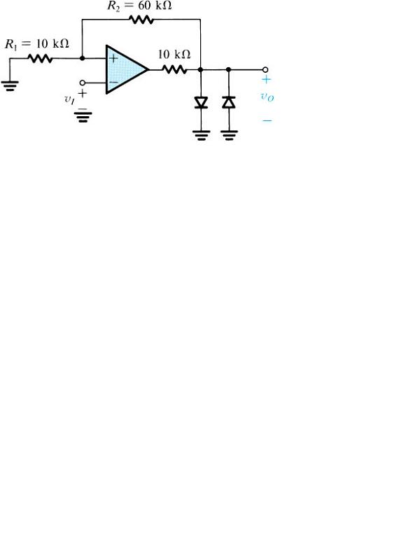
Diodes in the circuit shown in attached figure are assumed to have a constant 0.7 drop across them when they conduct. The op-amp is ideal. Its saturation limit is +/- 12V a) Sketch the transfer characteristic vo vs vi. b) What is the maximum diode current?

|
| |
|
|
|
|
thapap

Please log in to subscribe to thapap's postings.
Posted on 12-14-05 2:26
AM
Reply
[Subscribe]
|
Login in to Rate this Post:
0  ?
? 
|
| |
Sketch the voltage transfer characteristics of the attached circuit [ i.e. Vo vs Vi ] [ input trigger and Threshold are tied together with an input voltage Vi]

|
| |
|
|
thapap

Please log in to subscribe to thapap's postings.
Posted on 12-14-05 6:03
PM
Reply
[Subscribe]
|
Login in to Rate this Post:
0  ?
? 
|
| |
wow 52 views and still no response. common sajhaites... help me out here (O: ================================================== this time i really do not know them )O:
|
| |
|
|
acharya

Please log in to subscribe to acharya's postings.
Posted on 12-14-05 11:36
PM
Reply
[Subscribe]
|
Login in to Rate this Post:
0  ?
? 
|
| |
Let me know if you have an answer. I have the same problem in my homework due next week.
|
| |
|
|
thapap

Please log in to subscribe to thapap's postings.
Posted on 12-14-05 11:40
PM
Reply
[Subscribe]
|
Login in to Rate this Post:
0  ?
? 
|
| |
yup acharya jyu, after 24 hrs.. finally i got to it. (O: so what u paying for it (O: ===================================================== this time i found the answer
|
| |
|
|
thapap

Please log in to subscribe to thapap's postings.
Posted on 12-14-05 11:43
PM
Reply
[Subscribe]
|
Login in to Rate this Post:
0  ?
? 
|
| |
btw, if u r really serious about the answer send me email. I will send u the answer.
|
| |
|
|
Bhaute

Please log in to subscribe to Bhaute's postings.
Posted on 12-14-05 11:54
PM
Reply
[Subscribe]
|
Login in to Rate this Post:
0  ?
? 
|
| |
थापा जीलाई हेल्लो भन्न मात्र पसेको, अस्ति मेरो समस्या समाधान गरिदिएकोले :-) मेरो दिमागमा त अझै पनि त्यो अबरोधक (Resister) को अगाडि र पछाडि कसरी उही बिजुली बग्न सक्छ भनेर घुमिरहन्छ। ५ एम्पियर पसे पछि अबरोधकले खाएर २-४ एम्पियर मात्र बाहिर आउनु पर्ने जस्तो लाग्छ, अझै। :-) गुल्टिँदै गरम्..... :-) -भउते
|
| |
|
|
entropy

Please log in to subscribe to entropy 's postings.
Posted on 12-15-05 12:00
AM
Reply
[Subscribe]
|
Login in to Rate this Post:
0  ?
? 
|
| |
see this you might some some clue . positive feedback opamp config . http://www.ecircuitcenter.com/Circuits/op_comp/op_comp.htm
|
| |
|
|
thapap

Please log in to subscribe to thapap's postings.
Posted on 12-16-05 1:09
AM
Reply
[Subscribe]
|
Login in to Rate this Post:
0  ?
? 
|
| |
max diode current is gonna be (12-0.7)/(10k) - (0.7-0)/(60+10)k =11.63/10k - (0.7/70k) =1.163mA - 0.01mA =1.153mA
|
| |
|
|
chainreactor

Please log in to subscribe to chainreactor's postings.
Posted on 12-16-05 1:51
AM
Reply
[Subscribe]
|
Login in to Rate this Post:
0  ?
? 
|
| |
1st one is an example of Schmitt Trigger. So the x-fer characteristic will be that of Schmitt trigger with kind of hysteresis effect. And the 2nd one is a detailed diagram of 555 timer. So bro X-fer characteristic will be that of 555 timer with monostable vibrator in the configuration u have mentioned. I think so. It's been so long I studied this Ele. Ckt. subjects. Anyway.
|
| |
|
|
chainreactor

Please log in to subscribe to chainreactor's postings.
Posted on 12-18-05 1:55
AM
Reply
[Subscribe]
|
Login in to Rate this Post:
0  ?
? 
|
| |
2nd Ckt. is also Schmitt Trigger with +ve Vi offset
|
| |
